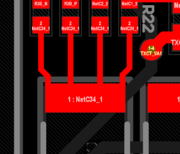
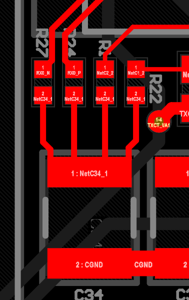
Hello everyone! I’m designing a PCB and I have some doubts about how to connect the 4 resistors at the top to capacitor C34. They are 4 traces, and all of them terminate at the same pad of the capacitor. As I have currently placed them, are they connected correctly? Or should I connect them in a different way?
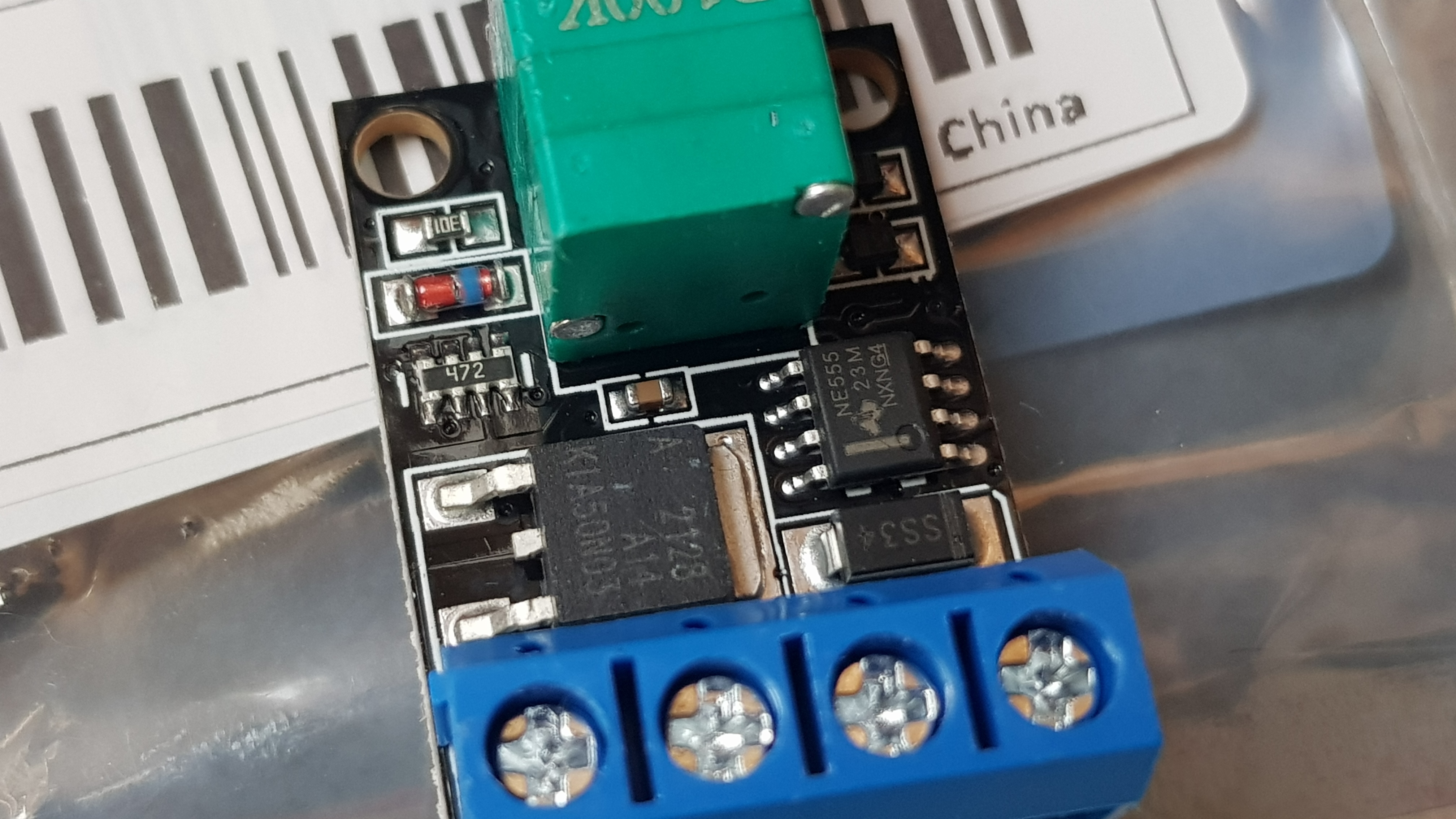
I bought a PWM Dimmer based on a 555 from AliExpress to regulate the brightness of a 12V 1A 1 meter LED strip, I already built one myself years ago on a perfboard but this one was the exact dimensions I needed for a project. I built mine from components from AliExpress and components found in old electronics so I thought nothing...
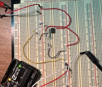
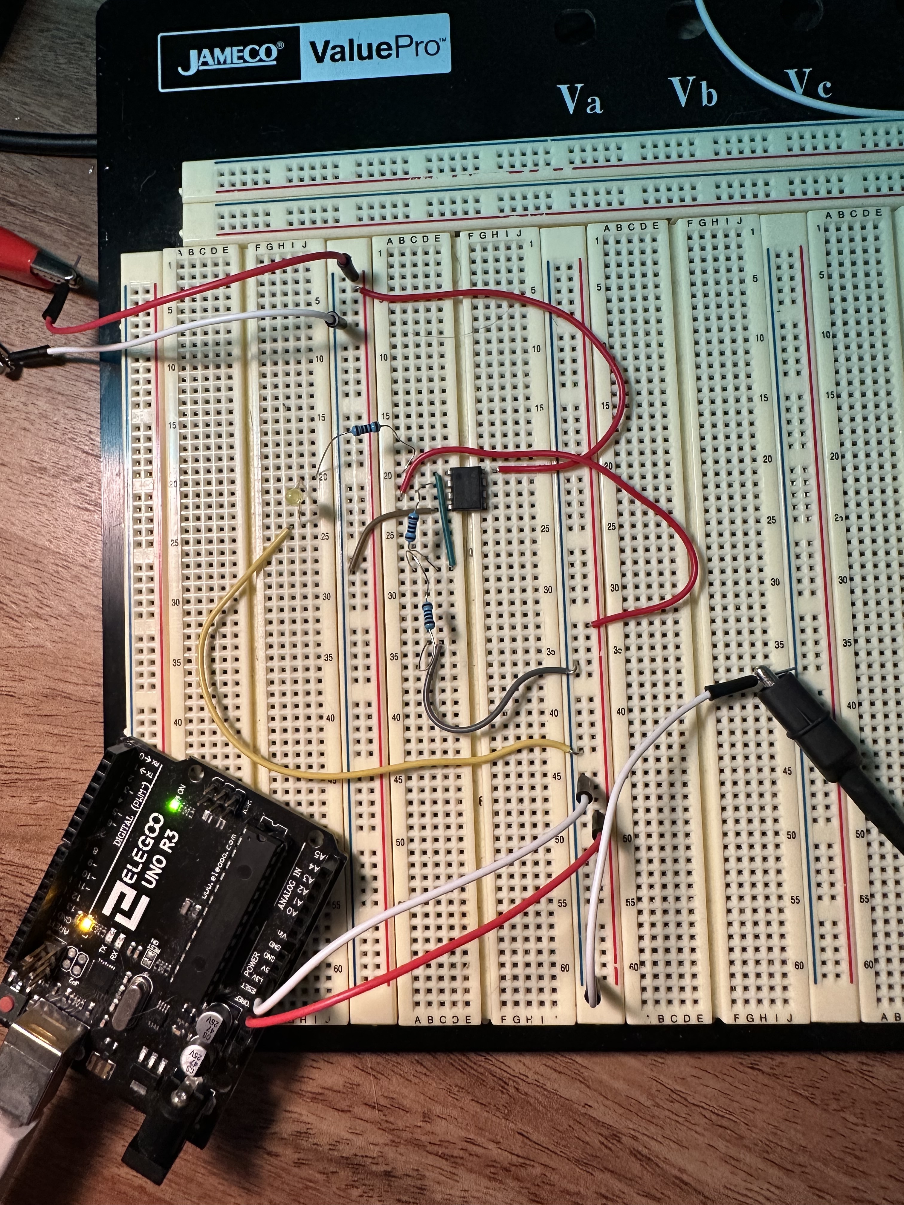
Since I never understood op-amps from reading or practicing problems I wanted to build a circuit to probe around and use different resistor values to set the amplification....
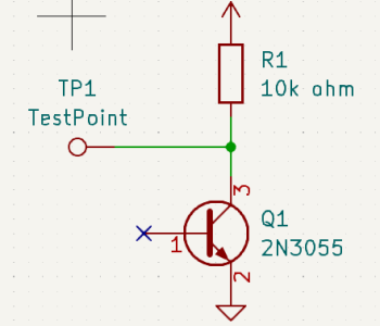
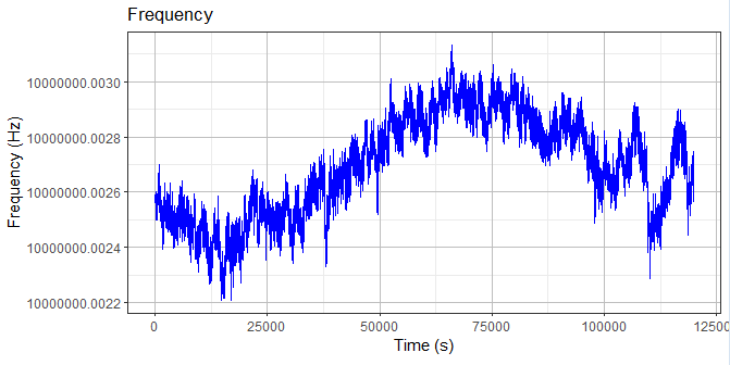
What I've done is take a large 2n3055 BJT NPN power transistor, and decap it (it is a large metal-can type). Then I carefully removed any coating from the exposed silicon (it typically has a dab of silicone potting compound on it)....
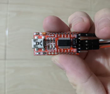
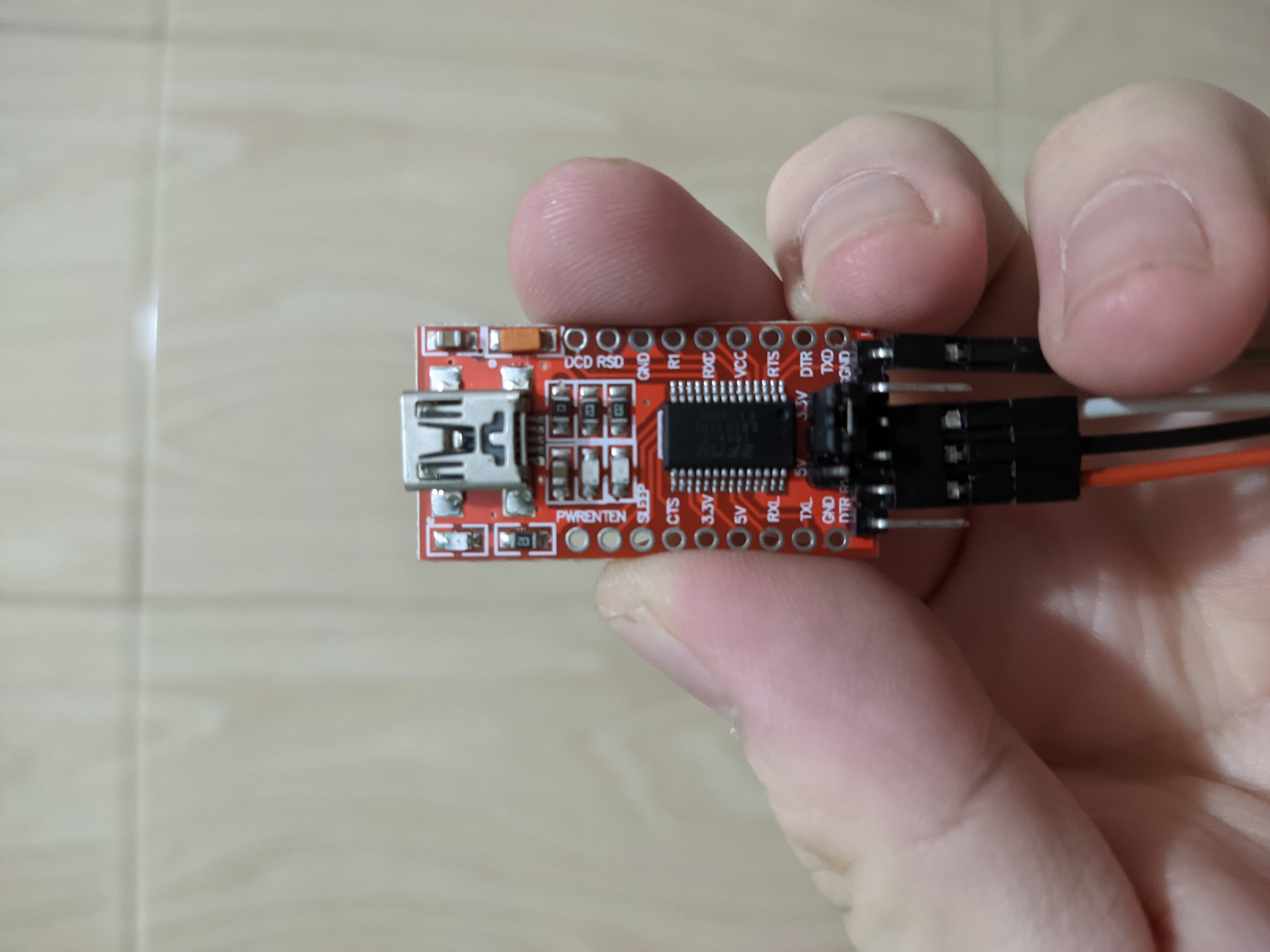
Bought it a long time ago and can't remember. There's a jumper cable and I remembered using it to flash something. I only dabble with Atmega32U4, Atmega328p and stm32 blue pill, so it's probably either of them....
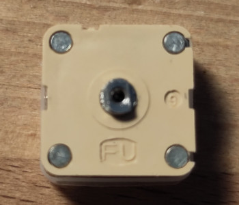
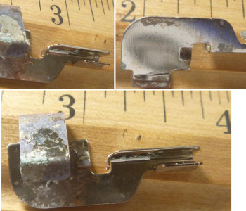
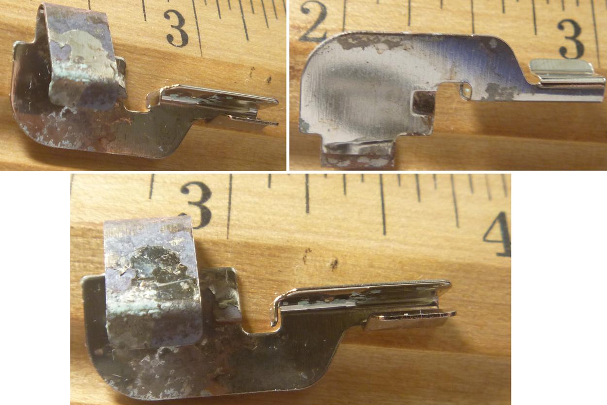
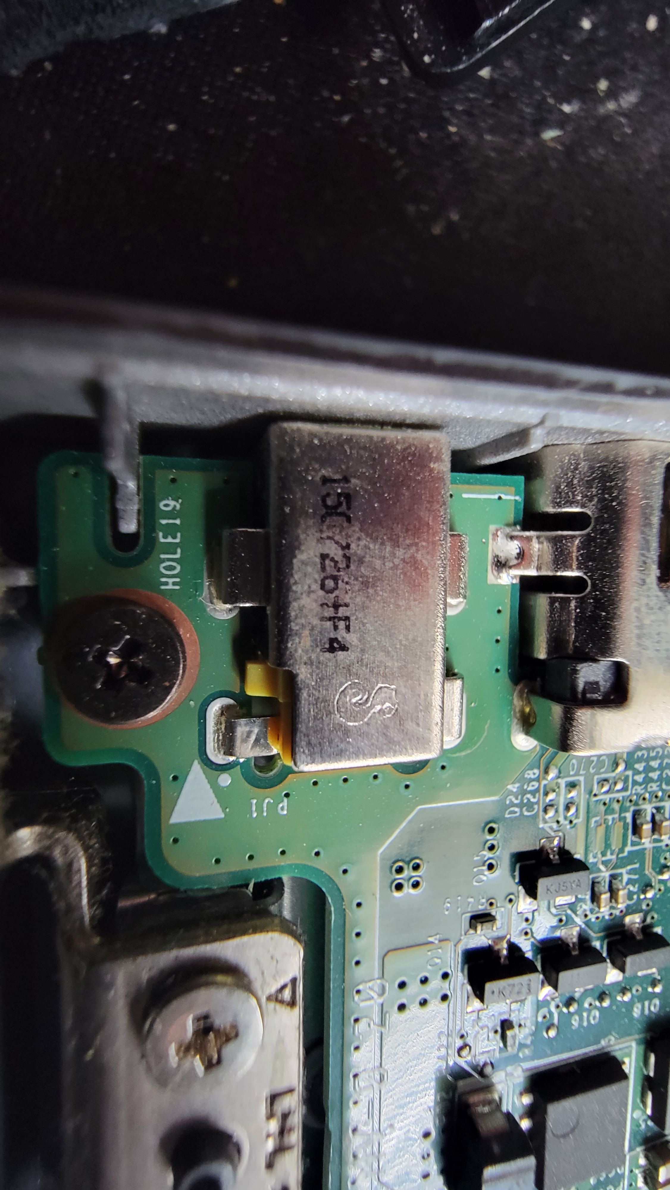
I have a acer c740 chromebook that has a cracked charging jack hoping I can find replacement part for it. Picture attached shows what's left of some number on it I think it's 150726+F4 not sure what the symbol is. The male end end is 3mm od 1.1mm Id if that helps.
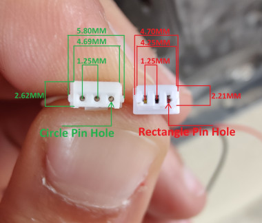
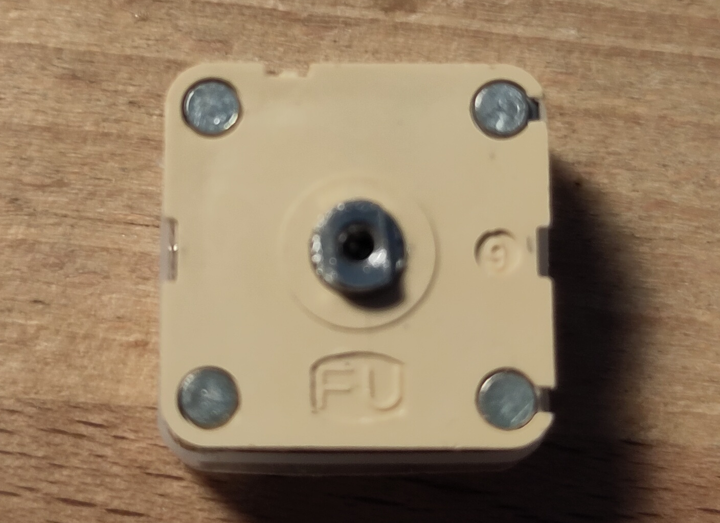
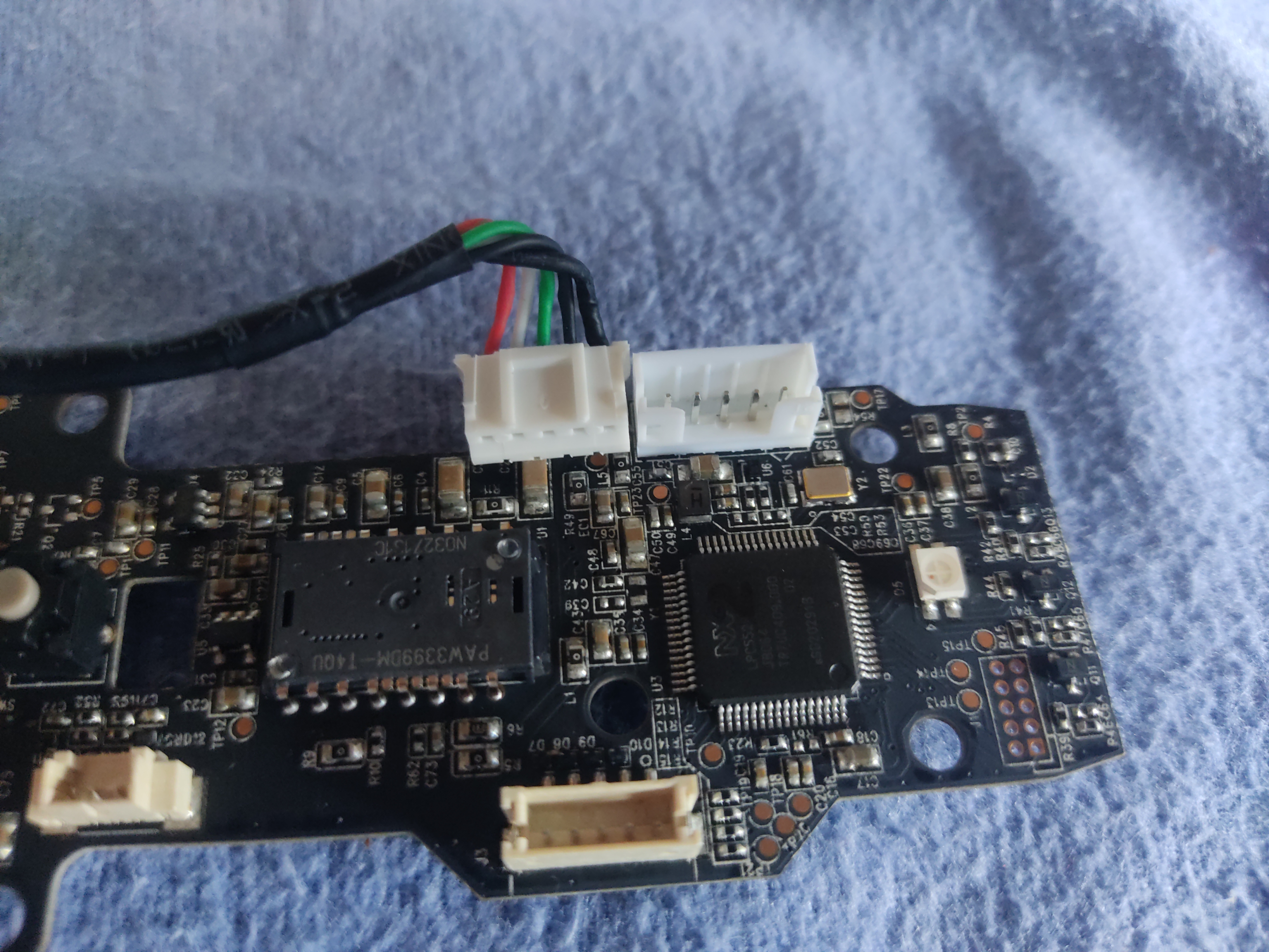
I'm working on adding extra access control to elevator calling buttons and i would like to identify the connector type of the wires connecting elevator buttons to the elevator panel...


